
Manufacturing success in the Western United States' industrial sectors depends on precision. Whether you're operating in oil and gas, aggregate processing, or recycling industries, components must meet exact specifications to ensure equipment reliability and operational efficiency. Precision CNC machining has become the cornerstone of modern manufacturing, enabling businesses to produce parts with tolerances measured in thousandths of an inch. This computer-controlled manufacturing process combines advanced technology with skilled craftsmanship to deliver consistent, high-quality results that traditional machining methods simply cannot match.
Understanding Precision CNC Machining Fundamentals
Precision CNC machining represents the intersection of computer programming, mechanical engineering, and material science. The process uses computer numerical control to guide cutting tools along precisely calculated paths, removing material from workpieces to create finished parts that meet stringent dimensional requirements.
Core Components of CNC Precision Systems
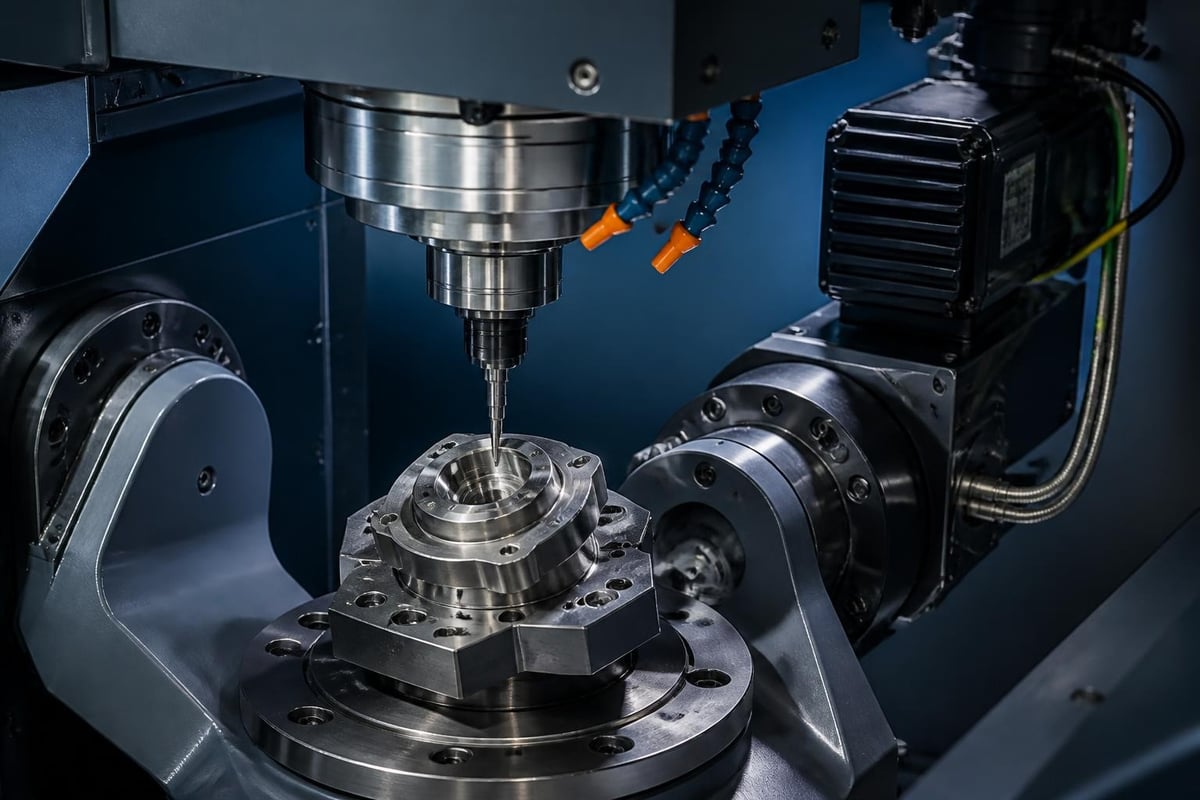
Modern CNC machines integrate several critical systems working in harmony. The control unit interprets G-code programming to direct tool movements with repeatability measured in microns. Servo motors provide the precise positioning required for tight tolerances, while feedback sensors continuously monitor tool position and adjust for any deviation.
Key system elements include:
- High-resolution encoders for position verification
- Rigid machine frames minimizing vibration and deflection
- Temperature-controlled environments preventing thermal expansion
- Precision spindles maintaining true rotation under load
- Advanced tooling systems ensuring consistent cutting geometry
The combination of these elements allows custom metal machining operations to achieve tolerances that would be impossible through manual methods. For industries requiring critical components, this precision directly translates to improved equipment performance and reduced downtime.
Tolerance Standards and Geometric Dimensioning
Achieving precision requires more than accurate equipment. It demands a comprehensive understanding of tolerance specifications and how they apply to functional requirements. The ASME product/standards page for Y14.5 provides the framework for communicating these requirements through geometric dimensioning and tolerancing (GD&T).
Implementing GD&T in Manufacturing
GD&T establishes a mathematical language for specifying the allowable variation in part geometry. This system goes beyond simple plus-minus tolerancing to control form, orientation, location, and runout characteristics that affect part function.
| GD&T Control | Application | Typical Tolerance Range |
|---|---|---|
| Flatness | Mating surfaces, sealing planes | 0.0005" – 0.005" |
| Perpendicularity | Shaft assemblies, mounting faces | 0.001" – 0.010" |
| Position | Bolt holes, pin locations | 0.002" – 0.020" |
| Concentricity | Rotating components, bearings | 0.0005" – 0.003" |
| Surface Finish | Hydraulic seals, wear surfaces | 16 – 125 microinches Ra |
For industrial equipment repair and replacement part manufacturing, proper GD&T application ensures components mate correctly and function as designed. This becomes particularly critical when reverse-engineering worn or damaged parts without original specifications.
Tolerance Stack-Up Analysis
Multiple tolerances in an assembly create cumulative variation that can affect final assembly fit and function. Engineers must analyze these tolerance chains to ensure worst-case scenarios remain within acceptable limits.
In practice, this means considering how tolerances on individual features combine. A shaft diameter tolerance of ±0.002", combined with a bearing bore tolerance of ±0.003", creates a potential clearance variation of 0.010". For applications requiring specific interference or clearance fits, this analysis becomes essential.
Material Considerations in Precision Work
Different materials respond uniquely to machining operations, affecting achievable tolerances and surface finishes. Understanding these characteristics enables metal fabrication process planning that accounts for material behavior.
Machinability and Precision Relationships
Harder materials generally hold tighter tolerances due to reduced tool deflection and wear. However, they require more rigid setups and often slower cutting speeds. Softer materials machine faster but may experience greater elastic deformation during cutting, affecting final dimensions.
Material-specific precision factors:
- Aluminum alloys: Excellent machinability, thermal expansion concerns, burr formation at edges
- Stainless steels: Work hardening during cutting, excellent surface finish potential, higher tool wear
- Carbon steels: Predictable machining behavior, wide tolerance capability, rust prevention required
- Bronze and brass: Superior surface finish, dimensional stability, ideal for bearing surfaces
- Exotic alloys: Specialized tooling required, slower production rates, exceptional precision possible
Recent research on numerical evaluation of cutting strategies for thin-walled parts demonstrates how material stiffness and machining approach interact to affect precision. Thin-walled components require specialized strategies to prevent deflection during cutting.
Thermal Management During Machining
Heat generation during cutting causes both tool and workpiece expansion, directly affecting dimensional accuracy. Precision CNC machining operations implement cooling strategies to minimize thermal effects.
Flood coolant systems remove heat and chips simultaneously, while through-spindle coolant delivery directs fluid precisely at the cutting zone. For extremely tight tolerance work, temperature-controlled shop environments maintain consistent thermal conditions throughout production runs.
Advanced Metrology and Quality Verification
Precision means nothing without the ability to measure and verify dimensions accurately. Modern metrology has evolved alongside machining capabilities, providing measurement resolution that exceeds manufacturing tolerances.
Coordinate Measuring Machines
CMM technology enables three-dimensional measurement of complex geometries with accuracies measured in tenths of thousandths. These computer-controlled measuring systems probe part surfaces, comparing actual dimensions against CAD models or inspection programs.
For manufacturing projects requiring documentation and certification, CMM inspection provides traceable measurement data supporting quality claims. First-article inspections establish process capability, while periodic checks ensure ongoing conformance.
The NIST publications and program pages on precision machining/metrology offer authoritative guidance on measurement standards and calibration procedures essential for maintaining accuracy.
On-Machine Measurement Systems
In-process measurement integrates metrology directly into the machining cycle, enabling real-time dimensional verification and process correction. Probing systems touch off on part features between machining operations, adjusting tool offsets to compensate for wear or thermal growth.
| Measurement Method | Resolution | Application | Advantages |
|---|---|---|---|
| Touch probe | 0.0001" | Feature location, size verification | Fast, automated, in-process |
| Laser scanning | 0.001" | Complex surface verification | Non-contact, full surface data |
| Vision systems | 0.0005" | Edge detection, pattern recognition | High-speed, multiple features |
| Air gauging | 0.00005" | Bore diameters, ID measurement | Extremely accurate, repeatable |
These technologies support the concept of adaptive machining, where measurement feedback drives automatic process adjustments. This closed-loop approach maintains precision even as tools wear or conditions change.
Process Planning for Precision Outcomes
Achieving consistent precision requires methodical planning before the first chip flies. Process engineers must consider tool selection, cutting parameters, fixture design, and operation sequencing to optimize dimensional accuracy.
Fixturing and Work Holding
Part stability during cutting directly affects achievable precision. Workpiece deflection under cutting forces causes dimensional variation, while vibration creates poor surface finish and accelerated tool wear.
Precision fixtures locate parts using the same datums specified in GD&T callouts, ensuring measurement references align with functional requirements. Clamping strategies distribute forces to minimize distortion, particularly critical for thin-walled or flexible components.
Effective fixturing principles include:
- Establish positive contact at datum features
- Support workpiece near cutting zones to resist deflection
- Distribute clamping forces across reinforced areas
- Minimize fixture elements interfering with tool access
- Design for consistent part loading and unloading
For heavy equipment repair applications, custom fixtures may be required for one-off replacement parts, balancing setup time against production requirements.
Tool Path Optimization
Computer-aided manufacturing (CAM) software generates tool paths controlling cutter movement. Optimized paths minimize tool deflection, distribute wear evenly, and sequence operations for dimensional accuracy.
Climb milling versus conventional milling affects surface finish and dimensional accuracy. Finish passes remove minimal material with light cutting forces, prioritizing surface quality over material removal rate. Tool engagement angle and radial depth of cut influence deflection and vibration.
Research on subtractive manufacturing of composite materials with robotic manipulators explores how unconventional machining platforms can achieve precision through optimized tool paths and cutting strategies, demonstrating principles applicable across machining technologies.
Multi-Axis Machining Capabilities
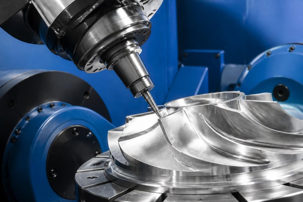
Complex geometries often require simultaneous multi-axis movement to maintain optimal tool orientation throughout cutting. Five-axis CNC machines tilt and rotate workpieces or cutting tools, accessing features from multiple angles in a single setup.
Benefits of Continuous Five-Axis Machining
Single-setup manufacturing reduces cumulative error from multiple setups while maintaining consistent datum references. Tool orientation optimization keeps cutting forces directed along the tool's strongest axis, reducing deflection and improving surface finish.
Five-axis advantages for precision work:
- Complex contoured surfaces machined without repositioning
- Shorter, more rigid cutting tools reach deep features
- Consistent surface finish across compound angles
- Reduced setup time and cumulative tolerance stack-up
- Improved access to undercuts and internal features
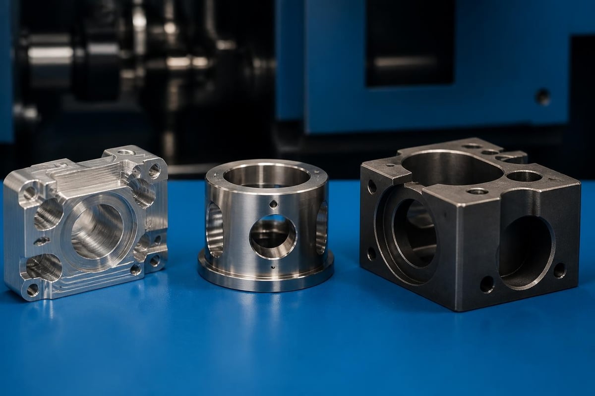
Industries such as oil & gas benefit from five-axis capabilities when manufacturing valve bodies, pump components, or specialized fittings requiring precision on multiple planes.
Quality Control Through Statistical Process Control
Maintaining precision across production runs requires systematic monitoring and analysis. Statistical process control (SPC) applies statistical methods to machining processes, identifying trends before they produce out-of-specification parts.
Implementing SPC in Machining Operations
Control charts track critical dimensions over time, plotting measurements against control limits calculated from process capability studies. Patterns in the data reveal tool wear, thermal drift, or other systematic variations requiring corrective action.
Process capability indices (Cp and Cpk) quantify a process's ability to produce parts within specification limits. Values above 1.33 indicate capable processes, while lower values signal the need for process improvement or specification review.
For commercial metal fabrication serving industries with strict quality requirements, SPC provides objective evidence of process control and capability, supporting certification and customer confidence.
First Article Inspection Protocols
The first part from a new setup undergoes comprehensive inspection, verifying all critical dimensions before production continues. This practice catches setup errors, programming mistakes, or tooling issues before producing scrap.
First article inspection reports (FAIR) document measurements, comparison to specifications, and conformance status. These reports become part of quality records, particularly important for industries requiring traceability and documentation.
Advanced Surface Finishing Techniques
Precision encompasses more than dimensional accuracy. Surface finish affects part function, particularly for sealing surfaces, bearing journals, and wear-resistant applications.
Surface Roughness Parameters
Surface texture is quantified through various parameters, with Ra (arithmetic average roughness) being most common. However, Rz (average maximum height), Rsk (skewness), and other parameters provide additional insight into surface characteristics.
The PTB standards and guidelines for surface metrology establish international measurement standards ensuring consistent surface characterization across manufacturers and inspection facilities.
| Finish Process | Achievable Ra | Application | Considerations |
|---|---|---|---|
| Rough turning | 125-250 μin | Non-critical surfaces | Fast, economical |
| Finish turning | 32-63 μin | General machined surfaces | Standard practice |
| Fine boring | 16-32 μin | Bearing bores, seal surfaces | Requires sharp tools |
| Grinding | 8-16 μin | Precision mating surfaces | Specialized equipment |
| Honing | 4-8 μin | Hydraulic cylinders, critical bores | Superior geometry |
| Lapping | 1-4 μin | Optical flats, gage blocks | Extremely fine finish |
For hydraulics manufacturing, surface finish directly affects seal performance and system efficiency. Cylinder bores require specific surface characteristics balancing low friction with adequate oil retention.
Cutting Tool Geometry and Finish
Tool nose radius, cutting edge preparation, and insert grade selection significantly influence surface finish. Larger nose radii generally produce smoother surfaces but may create chatter in unstable setups. Sharp cutting edges yield better finish but wear more rapidly than edge-prepared tools.
Tool materials range from carbide for general applications to polycrystalline diamond (PCD) for aluminum machining, each offering different combinations of wear resistance, edge sharpness, and cost. Selection depends on material being cut, required finish, and production volume.
Process Validation and Capability Studies
Before committing to production, manufacturers conduct capability studies verifying processes can consistently meet specifications. These studies collect measurement data under normal operating conditions, analyzing variation sources and process stability.
Conducting Effective Capability Studies
A proper capability study requires sufficient sample size to characterize process variation. Industry standards typically call for 25-30 consecutive parts measured at critical features. Data analysis identifies whether variation follows a normal distribution and calculates capability indices.
Study protocol includes:
- Verify measurement system accuracy and repeatability
- Machine parts under normal production conditions
- Measure critical features using calibrated instruments
- Calculate process mean and standard deviation
- Compute Cp, Cpk, and other capability metrics
- Document results and process parameters
Results guide decisions about process suitability, required inspection frequency, and potential improvement opportunities. Incapable processes require investigation into root causes, whether inadequate equipment, inappropriate tooling, or specification issues.
Continuous Improvement Methodologies
Precision CNC machining operations benefit from systematic improvement approaches. Six Sigma, lean manufacturing, and other methodologies provide frameworks for reducing variation and enhancing capability.
Root cause analysis investigates dimensional problems, drilling down from symptoms to underlying causes. Is a dimension consistently oversize due to tool deflection, thermal growth, or programming offset error? Identifying true causes enables effective corrective action.
Integration with Complementary Manufacturing Processes
Precision CNC machining rarely exists in isolation. It integrates with welding, fabrication, and assembly operations to create complete manufactured assemblies. Understanding these interfaces ensures dimensional control throughout production.
Machining After Welding Considerations
Welding introduces heat, distortion, and residual stresses affecting machined dimensions. Strategic process sequencing manages these effects. Rough machining before welding provides material for final machining after welding, compensating for distortion.
Heat treatment or stress relieving after welding removes residual stresses before finish machining, preventing subsequent dimensional changes. For welding service company operations, coordinating welding and machining sequences maintains precision through all manufacturing stages.
Combination Manufacturing Strategies
Modern manufacturing increasingly combines additive and subtractive processes. Near-net-shape casting or additive manufacturing creates basic geometry, while precision CNC machining adds critical features and final dimensions.
This hybrid approach balances material utilization, production time, and dimensional accuracy. Complex internal passages might be cast or additively manufactured, while bearing surfaces, seal grooves, and mounting faces receive precision machining.
Precision Machining for Specific Industry Applications
Different industries present unique precision machining challenges. Understanding sector-specific requirements enables tailored solutions delivering optimal results.
Oil and Gas Component Manufacturing
Equipment operating in oil and gas applications endures extreme pressures, temperatures, and corrosive environments. Components must meet stringent specifications ensuring reliable performance under harsh conditions.
Valve bodies require precise port geometries and sealing surfaces. Pump components demand tight clearances maintaining efficiency while accommodating thermal expansion. Drilling equipment faces impact loads necessitating precision manufacture from high-strength materials.
Aggregate and Mining Equipment Parts
Heavy equipment in aggregate processing experiences severe wear and impact. Replacement parts must match original specifications while potentially offering improved wear resistance through advanced materials or surface treatments.
Crusher components, conveyor system parts, and screening equipment require precision machining despite their size and weight. Large-format CNC machines handle these components, maintaining tolerance control across substantial dimensions.
Industrial Manufacturing Support
General industrial manufacturing relies on precision components for production equipment, processing machinery, and material handling systems. Gearbox components, shaft assemblies, and custom tooling require careful machining ensuring long service life and consistent performance.
For businesses throughout the Western United States, access to precision CNC machining capabilities supports production continuity. When equipment fails, rapid manufacture of replacement parts minimizes downtime and production losses.
Emerging Technologies in Precision Machining
The field continues evolving as new technologies enhance capabilities and expand precision boundaries. Staying current with developments positions manufacturers for future opportunities.
Adaptive Control and Artificial Intelligence
Machine learning algorithms analyze sensor data in real-time, adjusting cutting parameters to maintain optimal conditions. Systems learn from experience, refining strategies based on outcomes and building databases of best practices for various materials and geometries.
Advanced research on design and analysis of an ultra-precision smart cutting tool demonstrates how instrumented tooling enables closed-loop control, measuring forces and vibration to guide parameter adjustment and prevent dimensional deviation.
Digital Twin Technology
Virtual models of physical machines and processes enable simulation before actual cutting. Digital twins predict outcomes, optimize parameters, and identify potential problems in the virtual environment, reducing physical trial-and-error and scrap.
These models incorporate machine characteristics, tool behavior, material properties, and cutting physics, creating accurate predictions of dimensional results, surface finish, and tool life. As simulations improve, they increasingly guide process planning and troubleshooting.
Selecting Precision Machining Partners
Not all machining services offer equivalent precision capabilities. Evaluating potential partners requires examining equipment, expertise, quality systems, and track record.
Capability Assessment Criteria
Modern CNC equipment alone doesn't guarantee precision outcomes. Operator skill, process knowledge, and quality culture equally contribute to consistent results. Visiting facilities provides insight into organization capabilities and commitment to precision.
Evaluation factors include:
- Equipment age, condition, and maintenance practices
- Quality system certifications and audit results
- Measurement equipment and calibration programs
- Operator training and experience levels
- Process documentation and control procedures
- Examples of similar precision work completed
- Customer references and testimonials
For businesses seeking industrial services company support, verifying precision machining capabilities ensures partners can meet demanding specifications.
Communication and Documentation
Precision work requires clear communication of requirements. Complete drawings with proper GD&T, material specifications, and finish requirements prevent misunderstandings. Detailed quotations clarifying tolerances, inspection methods, and acceptance criteria establish mutual expectations.
Documentation throughout production creates records supporting traceability. Inspection reports, material certifications, and process traveler documents provide evidence of conformance and support quality audits or failure investigations.
Precision CNC machining delivers the tight tolerances and consistent quality that modern industrial operations demand, combining advanced technology with skilled craftsmanship to produce components meeting exact specifications. Whether you're in oil and gas, aggregate processing, recycling, or general manufacturing, access to reliable precision machining capabilities keeps your equipment running and your operations productive. LTJ Industrial Services brings comprehensive machining, welding, and fabrication expertise to businesses throughout the Western United States, delivering the precision components and quick turnaround times that minimize downtime and maximize productivity. Contact our team to discuss your precision machining requirements and experience the difference that skilled craftsmanship and modern technology make for your critical manufacturing needs.