
Industrial equipment operating in harsh environments faces constant wear from abrasion, impact, and corrosion. Replacing worn components creates expensive downtime and consumes capital budgets quickly. Hardfacing offers a proven solution by applying wear-resistant alloy layers to critical surfaces, extending service life by 300% or more in many applications. This welding overlay technique deposits specialized filler metals onto base materials, creating a hardened surface that withstands extreme operating conditions while preserving the structural integrity of the underlying component.
Understanding Hardfacing Fundamentals
Hardfacing involves depositing a layer of wear-resistant material onto a base metal surface through welding processes. The deposited material creates a protective barrier that absorbs wear while the base metal provides structural support.
This technique differs fundamentally from heat treatment or case hardening. Rather than modifying the existing surface chemistry, hardfacing adds an entirely new metallurgical layer with properties specifically engineered for wear resistance. The base material can remain relatively soft and ductile, providing toughness and shock absorption, while the hard overlay resists abrasion and erosion.
Primary Wear Mechanisms Addressed
Different industrial environments create distinct wear patterns. Understanding these mechanisms helps engineers select appropriate hardfacing alloys and processes.
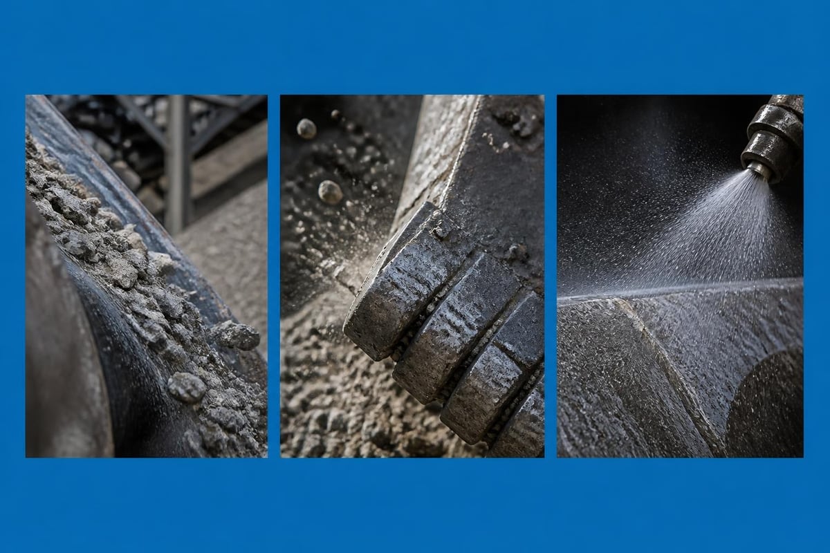
Abrasive wear occurs when hard particles slide across metal surfaces, removing material through cutting or plowing action. This dominates in aggregate processing, mining conveyors, and earthmoving equipment. Impact wear results from repeated high-energy collisions that fracture or deform surface material, common in crusher components and hammer mills. Erosive wear happens when particles or fluids strike surfaces at acute angles, as seen in slurry pumps and pneumatic conveying systems.
Corrosive environments accelerate wear through chemical attack combined with mechanical action. Oil and gas operations frequently encounter this combination in downhole tools and processing equipment.
Hardfacing Alloy Selection and Classification
Choosing the correct filler metal represents the most critical decision in any hardfacing application. The AWS A5.13/A5.13M specification provides standardized classifications for surfacing electrodes and rods.
| Alloy Family | Primary Carbides | Hardness Range (HRC) | Best Applications |
|---|---|---|---|
| Iron-based | Fe₃C, Cr₇C₃ | 35-55 | Metal-to-metal wear, moderate abrasion |
| Chromium carbide | Cr₇C₃, Cr₃C₂ | 55-63 | High abrasion, mining equipment |
| Tungsten carbide | WC, W₂C | 58-65 | Extreme abrasion, earthmoving tools |
| Cobalt-based | Complex carbides | 38-55 | High temperature, corrosion resistance |
Iron-Based Hardfacing Alloys
These economical options suit applications involving moderate abrasion or metal-to-metal sliding. Carbon content typically ranges from 0.5% to 4.0%, with chromium additions between 12% and 30%. They provide excellent deposition rates and good crack resistance.
Martensitic iron-based alloys harden through transformation during cooling, achieving 40-50 HRC without preheating requirements. Austenitic formulations remain tough and work-harden under impact, making them ideal for crusher manganese liners and railcar components.
Chromium Carbide Composite Alloys
The workhorse of industrial hardfacing applications, chromium carbide alloys combine high hardness with reasonable toughness. Complex carbide networks create exceptional abrasion resistance while the matrix provides fracture resistance.
These alloys contain 25%-35% chromium, forming Cr₇C₃ and Cr₃C₂ carbides distributed throughout an iron or nickel matrix. Multi-pass applications build thickness economically while maintaining hardness levels between 58-63 HRC. Recent research on multi-carbide reinforced layers demonstrates how carbide volume fraction and distribution affect wear performance across different loading conditions.
Tungsten Carbide Overlay Systems
For maximum abrasion resistance, tungsten carbide composites deliver unmatched performance. These systems embed angular WC particles (typically 50%-60% by weight) in a tough matrix material.
Tube-fed systems pneumatically deliver carbide particles into the weld pool during open-arc welding. This produces economical overlays suitable for large surface areas. Composite rod electrodes incorporate carbide particles within the consumable itself, providing better control over carbide distribution and easier positioning for complex geometries.
Cast tungsten carbide overlays achieve hardness above 65 HRC but require careful thermal management to prevent cracking. These find applications in tillage points, dredge cutterheads, and slurry pump components.
Hardfacing Process Selection
Multiple welding processes can deposit hardfacing materials, each offering distinct advantages for specific applications and geometries.
Shielded Metal Arc Welding (SMAW)
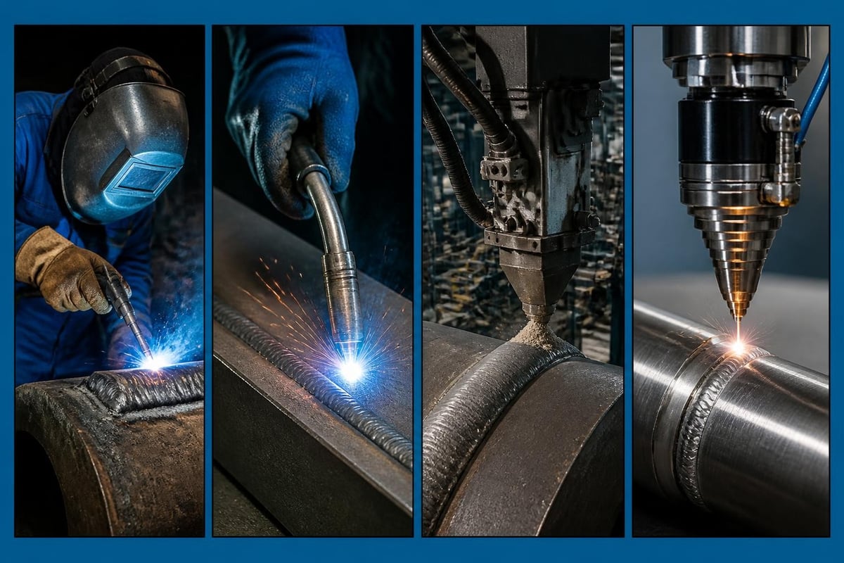
Manual stick electrode hardfacing remains popular for field repairs and complex geometries. Operators achieve precise control over heat input and deposit location without auxiliary equipment requirements.
Standard 1/8-inch and 5/32-inch electrodes suit most applications. Larger diameter electrodes (3/16-inch and 1/4-inch) increase deposition rates on flat or slightly curved surfaces. Certified welding services ensure proper technique, inter-pass temperature control, and defect-free deposits.
Gas Metal Arc Welding (GMAW)
Semi-automatic wire-feed processes dramatically increase productivity on repetitive hardfacing tasks. Flux-cored wires dominate production hardfacing because they combine high deposition rates with excellent metallurgical control.
Self-shielded flux-cored wires eliminate external gas requirements for field applications. Gas-shielded formulations provide smoother arc characteristics and reduced spatter in shop environments. Deposition rates reach 8-15 pounds per hour compared to 2-4 pounds per hour with SMAW.
Submerged Arc Welding (SAW)
The highest deposition rate process, submerged arc welding deposits hardfacing under a blanket of granular flux. This produces clean, uniform overlays with minimal oxidation and excellent fusion characteristics.
Multiple-wire SAW systems apply hardfacing at rates exceeding 40 pounds per hour. Automated operation ensures consistent layer thickness across large flat surfaces like wear plates and crusher liners. The process requires positioning equipment but delivers unmatched productivity for high-volume production.
Specialty Processes
Plasma transferred arc (PTA) welding produces extremely thin, precise overlays with minimal dilution. Heat-affected zones remain small, making PTA ideal for heat-sensitive base materials or applications requiring specific surface chemistry.
Laser cladding delivers even finer control, depositing layers as thin as 0.020 inches with dilution below 5%. This precision suits valve seating surfaces, hydraulic ram surfaces, and other applications where dimensional control is critical.
Application Engineering and Design Considerations
Successful hardfacing requires careful attention to base material compatibility, thermal management, and layer design. Poor planning leads to cracking, spalling, or premature failure.
Base Material Preparation
Surface cleanliness directly impacts fusion quality and defect formation. Remove all rust, scale, paint, oil, and contamination through grinding or waterjet cutting for precision edge preparation. Inspect prepared surfaces for cracks or defects that could propagate during welding.
Preheat requirements depend on base material carbon equivalent and section thickness. Low-alloy steels with carbon equivalent above 0.45% typically require preheat between 300°F and 500°F. High-carbon tool steels may demand 600°F or higher to prevent hardening and cracking in the heat-affected zone.
The AWS practical guidance document provides detailed recommendations for welding procedures and preheat requirements based on material chemistry and application severity.
Layer Design and Build Sequence
Single-layer deposits rarely exceed 1/4-inch thickness due to cracking risk in high-hardness alloys. Multi-layer systems build functional thickness while managing residual stress.
- Buffer layer: A tough, lower-hardness material applied first to absorb stress and prevent crack propagation from the base metal
- Intermediate layers: Build thickness using moderate-hardness alloys with good crack resistance
- Final wear layer: High-hardness material applied as the last 1-3 passes to maximize abrasion resistance
This layered approach controls dilution while creating a gradual hardness transition. Each layer should be thoroughly cleaned between passes to prevent slag inclusions and ensure sound fusion.
Dilution Management
The weld pool mixes deposited filler metal with melted base material, reducing hardness and altering chemistry in the first layer. Typical dilution ranges from 15% to 40% depending on process parameters and joint geometry.
Minimizing dilution preserves alloy properties through:
- Using smaller diameter electrodes or lower wire-feed speeds
- Increasing travel speed to reduce heat input
- Employing stringer beads rather than weave patterns
- Selecting processes with concentrated heat sources (PTA, laser)
Applications requiring specific surface chemistry often specify maximum allowable dilution percentages. Metallographic testing verifies actual dilution and confirms hardness specifications.
Industry-Specific Hardfacing Applications
Different sectors encounter unique wear challenges requiring tailored hardfacing solutions. Understanding industry-specific requirements optimizes alloy selection and process parameters.
Mining and Aggregate Processing
Crushing, screening, and conveying equipment experiences severe abrasive wear from quartz-bearing minerals. Hardfacing extends component life 4-10 times compared to carbon steel alternatives.
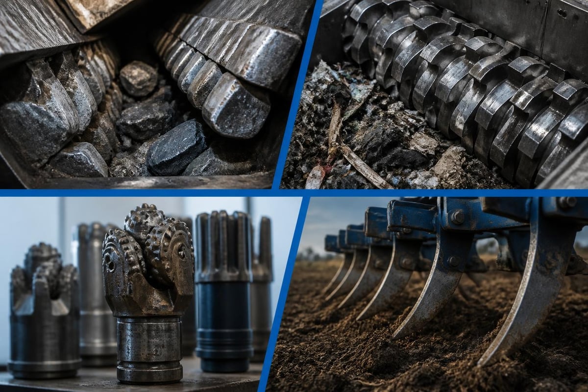
Crusher manganese jaws and cones benefit from iron-based work-hardening alloys that toughen under impact while resisting abrasion. Screen decks and chutes require chromium carbide overlays to withstand continuous particle impingement. Conveyor components including pulleys, idlers, and transfer points use tungsten carbide composites for maximum abrasion resistance.
Mining equipment fabrication integrates hardfacing into new component manufacturing, applying wear-resistant layers during initial fabrication rather than waiting for field failure.
Recycling and Scrap Processing
Recycling equipment handles mixed materials containing extreme abrasives like sand, concrete, and embedded carbides. This creates accelerated wear compared to virgin material processing.
Shredder hammers, anvils, and grates require impact-resistant hardfacing formulations. Chromium carbide alloys with controlled carbon content (2.5%-3.5%) balance hardness against fracture toughness. Recycling equipment repair and welding services restore worn components through hardfacing buildup, often achieving service life exceeding new OEM parts.
Oil and Gas Production
Downhole tools and surface equipment face combined abrasive, erosive, and corrosive wear in harsh environments. Specialized hardfacing alloys address multiple degradation mechanisms simultaneously.
Drill collars, stabilizers, and kellys use tungsten carbide hardbanding to protect threads and provide gauge maintenance. Production equipment including wellheads, choke valves, and frac equipment requires cobalt-based or nickel-based alloys for corrosion resistance at elevated temperatures.
Agricultural and Earthmoving Equipment
Tillage tools, bucket teeth, and ripper shanks encounter soil abrasion intensified by quartz and rock contamination. Hardfacing these components during manufacturing or rebuild cycles dramatically reduces replacement frequency.
Quality Control and Performance Verification
Ensuring hardfacing quality requires systematic inspection and testing protocols. Defects compromise wear resistance and can lead to catastrophic failure under load.
Visual and Dimensional Inspection
Examine completed overlays for surface cracks, porosity, undercut, and incomplete fusion. Acceptable surface roughness varies by application, but most specifications limit profile height to 1/8-inch for machined surfaces.
Measure overlay thickness using ultrasonic testing or destructive sectioning on qualification samples. Verify coverage extends beyond wear zones with appropriate margin for grinding and finishing operations.
Hardness Testing and Metallurgical Analysis
Rockwell C-scale hardness testing confirms alloy performance matches specifications. Test multiple locations across the deposited area to verify consistency. Most hardfacing applications specify minimum hardness values rather than ranges, recognizing that excessive hardness can increase brittledness.
Metallographic examination reveals microstructure, dilution levels, and carbide distribution. Cross-sections through the deposit verify layer thickness, fusion quality, and absence of defects. This destructive testing qualifies procedures before production application.
| Test Method | Application | Acceptance Criteria |
|---|---|---|
| Visual inspection | All deposits | No cracks, complete coverage |
| Hardness survey | Production verification | Meets minimum specification |
| Ultrasonic thickness | Large area overlays | ±0.030" of specified thickness |
| Metallography | Procedure qualification | Sound fusion, acceptable dilution |
| Wear testing | Critical applications | Meets service life targets |
Accelerated Wear Testing
Laboratory wear tests predict field performance and compare alternative alloy systems. ASTM G65 dry sand rubber wheel testing quantifies abrasion resistance through standardized procedures. Results correlate well with field experience in many applications.
Pin-on-disk testing evaluates metal-to-metal wear characteristics. Slurry pot testing simulates erosive conditions. Custom fixtures replicate specific application geometries and loading conditions for critical components.
Economic Analysis and Total Cost Optimization
Hardfacing decisions should balance initial application costs against extended service life and reduced downtime. Simple payback calculations often overlook significant operational benefits.
Cost Components and Variables
Material costs vary dramatically across alloy families. Iron-based consumables cost $3-$8 per pound, chromium carbides range from $8-$15 per pound, and tungsten carbide composites reach $20-$40 per pound. Labor represents 40%-70% of total applied cost in most applications.
Process selection impacts productivity and labor requirements. Manual SMAW deposits 2-4 pounds per hour, while automated SAW achieves 40+ pounds per hour. Equipment investment must be amortized across sufficient production volume to justify capital expenditure.
Service Life Extension Value
A $500 hardfacing application that doubles equipment life from 6 months to 12 months delivers immediate economic returns. However, the real value often lies in:
- Reduced downtime for component changeout (8-40 hours depending on equipment)
- Eliminated emergency repairs with associated premium costs and schedule disruption
- Decreased inventory requirements for spare components
- Lower total installed cost compared to exotic base material alternatives
Components lasting 18-24 months between rebuilds enable predictable maintenance scheduling during planned shutdowns rather than reactive emergency repairs.
Build vs. Buy Decisions
Organizations must evaluate in-house hardfacing capabilities against outsourced services. Small to medium operations often lack the specialized equipment, qualified welders, and engineering expertise to optimize hardfacing applications.
Custom metal fabrication shops with hardfacing expertise provide turnkey solutions including engineering analysis, process development, application, and quality verification. This converts fixed costs into variable costs while accessing specialized capabilities.
Process Control and Welding Parameters
Achieving consistent hardfacing quality requires tight control over welding variables. Process specifications should define acceptable parameter ranges for each variable affecting deposit properties.
Heat Input Management
Heat input, measured in kilojoules per inch, directly affects dilution, cooling rate, and resulting microstructure. The formula H = (60 × V × A) / (1000 × S) calculates heat input where V is voltage, A is amperage, and S is travel speed in inches per minute.
Most hardfacing applications specify heat input ranges between 15-45 kJ/in depending on alloy system and base material. Exceeding maximum values increases dilution and may cause cracking. Insufficient heat input produces incomplete fusion and slag entrapment.
Inter-pass temperature control prevents excessive heat buildup that promotes cracking in high-carbon alloys. Specifications typically limit maximum inter-pass temperature to 400°F-600°F. Temperature-indicating crayons or infrared thermometers verify compliance.
Deposition Technique Variables
Travel speed, electrode angle, and weave width significantly influence deposit geometry and properties. Consistent technique produces uniform thickness and surface profile.
- Maintain constant travel speed within ±10% of specified value
- Hold electrode angle at 5-15° in travel direction for SMAW
- Limit weave width to 3× electrode diameter to control dilution
- Overlap adjacent beads 30%-50% to ensure complete coverage
Stringer bead technique minimizes dilution and heat input compared to wide weave patterns. This proves critical for high-alloy deposits where chemistry control matters.
Filler Metal Storage and Handling
Moisture absorption in flux-cored wires and stick electrodes causes porosity and hydrogen cracking. Store consumables in climate-controlled environments maintaining relative humidity below 50%.
Low-hydrogen electrodes require baking at 700°F-800°F for 1-2 hours before use if exposed to ambient conditions. Holding ovens maintain 250°F-300°F during production to prevent moisture pickup. Flux-cored wires should remain in original sealed packaging until use.
Repair and Rebuild Strategies
Hardfacing excels at rebuilding worn components to original or improved specifications. Strategic repair programs transform preventive maintenance from cost center to profit generator.
Damage Assessment and Repairability Analysis
Not all worn components justify hardfacing repair. Evaluate structural integrity, base material condition, and dimensional accuracy before committing resources.
Examine the component for fatigue cracks, stress corrosion, or metallurgical damage extending beyond surface wear. Cracks propagating through section thickness often make repair uneconomical. Measure remaining wall thickness to verify adequate material remains after weld preparation.
Dimensional restoration through hardfacing buildup proves economical when worn areas are localized rather than uniform. Hydraulic cylinder rods, crane wheels, and shaft journals frequently qualify for hardfacing repair when journals have worn undersized through operation.
Buildup Procedure Development
Heavy buildup applications require careful procedure qualification to prevent cracking and distortion. Deposits exceeding 1/4-inch thickness should incorporate lower-alloy buffer layers before applying final wear-resistant materials.
Stress relief treatments between layer groups (every 1/2-inch to 1-inch of buildup) control residual stress in thick deposits. Holding components at 1100°F-1200°F for 1 hour per inch of thickness reduces crack susceptibility. Post-weld heat treatment after final layers further improves component reliability.
The relationship between tight tolerance machining and hardfacing matters for precision rebuilds. Coordinate machining allowances with expected overlay thickness, accounting for distortion and uneven buildup. Plan 1/8-inch to 1/4-inch machining stock beyond final dimension.
Coating and Finishing Considerations
Most hardfacing applications require minimal finishing beyond removal of high spots and spatter. However, certain applications demand specific surface profiles or additional protective coatings.
Machining hardfacing alloys requires carbide tooling and rigid setups. Chromium carbide and tungsten carbide overlays wear conventional high-speed steel tools rapidly. Grinding proves more economical than turning for hardness above 58 HRC. Surface grinding with aluminum oxide or ceramic wheels produces smooth finishes suitable for dynamic sealing surfaces.
Powder coating versus paint durability comparisons matter less on hardfaced surfaces since the alloy itself provides corrosion resistance. Applications requiring additional corrosion protection should evaluate whether coating adhesion to high-hardness surfaces meets service requirements.
Hardfacing delivers measurable economic value by extending equipment life, reducing downtime, and eliminating repetitive component replacement costs across industrial applications. Proper alloy selection, process control, and quality verification ensure reliable performance in the most demanding service environments. Whether you need field repairs on aggregate processing equipment, rebuilding worn mining components, or engineering custom hardfacing solutions for unique applications, LTJ Industrial Services combines certified welding expertise with comprehensive fabrication and machining capabilities to deliver results throughout the Western United States.